Background
Data Acquisition
The process of converting analog signals (e.g. voltages) to values in a computer program is one of the core components of modern instrumentation and communication systems. The other component is of course the computer itself, where the data is processed and displayed or otherwise acted on. This process can also work in the opposite direction. The computer can calculate a desired stimulus which can then be converted to an analog signal and applied (perhaps via a transducer) to the system being analyzed.
The process of converting an analog signal to a digital value in a computer program variable is called Analog to Digital (A/D) Conversion. Similarly converting a digital variable to an analog value is called Digital to Analog (D/A) Conversion. A general term for reading and writing external analog values is Data Acquisition.
Each A/D conversion results in a single digital value. To represent a constant voltage, one value is all we need, but to represent a continuous, time-varying voltage signal would require an infinite number of values. If the signal is sufficiently smooth, we can approximate it with a finite set of samples and use interpolation to fill in the intermediate values. We usually acquire these samples at regularly spaced time intervals.
The density of samples or sampling rate required to represent a signal depends both on how smooth the signal is and on how accurate our representation must be. As an example, consider digital audio signals. CD's use a sampling rate of 44.2 kHz to provide high quality sound while cell phones make do with rates of around 8 kHz.
The DAQ Card and Labview
There are two sets of A/D and D/A converters in the Lab PC. One is the audio interface (or sound card), the other is called a Data Acquisition Card (or DAQ card for short). Specifications for the DAQ card can be found on the 6251 DAQ Card data sheet.
We also have a program called Labview which provides access to the A/D conversion hardware, as well as programmable signal processing and display hardware. We will use Labview for most of our laboratory automation and digital signal processing examples. Labview allows us to take a signal, convert it to a sequence of samples perform mathematical operations on them, and display the results on the PC screen. We can also generate samples of a function by computing their values and convert them to voltages to form an output signal.
This is just what our lab instruments do, only with continuous functions rather than samples. If we can represent the information in our signal by a set of samples, then we can use Labview and the DAQ card to make and display automatically the same measurements we made manually using conventional instruments. We can also have Labview perform the calculations necessary to convert the raw measurements into the desired information, rather than having to do them by hand or in Matlab.
The DAQ Interface Module
Since there are a total of 10 DAQ signals that we are interested in (8 A/D channels and 2 D/A channels), the DAQ card has an entire interface module to itself. This module is located in rightmost interface slot on the breadboard and is labeled "MOD03 - NI 6251 Interface Module."
The two Digital-to-Analog converter outputs are connected directly to pins on the interface strip. However, there are a couple of reasons not to connect directly to the Analog-to-Digital inputs:
-
The maximum full-scale input voltage for the DAQ card is 10 V. Since the power supply can produce voltages up to 20 V, we need a larger input range on at least some of the inputs.
-
The input impedance of the DAQ card is extremely high. This means that leakage currents can charge the input capacitance faster than they can be drained off, resulting in saturation unless the input is terminated.
To address these problems there is a voltage divider between each pin on the interface strip and the corresponding DAQ card input. For inputs 0-3 the divider ratio is 10:1, and for inputs 4-7 it is 1:1 (i.e. no attenuation). For all inputs the sum of the resistor values is 1 MΩ.
The figure below is an abbreviated circuit diagram of the DAQ Interface Module.
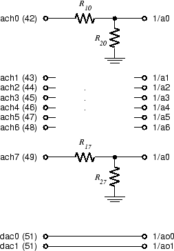
The circuitry for channels ach1 through ach6 (indicated by the ellipsis) is the same as channels ach0 and ach7. The signals ach0-7 are the A/D input terminals on the interface connector socket strip and dac0 and dac1 are the D/A output terminals. 1/a0-7 are the A/D inputs to the DAQ card and 1/ao0 and 1/ao1 are the D/A outputs.